TYPES OF OPTICAL FIBER AND THEIR CHARACTERISTICS:-
1)- Single-Mode optical fiber
2)- Multimode optical fiber with stepped index
3)- Multimode optical fiber with graded-index
SINGLE -MODE OPTICAL FIBER :-
1)- This type of optical fiber transmits only mode of light.
2)- it can carry only one wavelength of light across its length.
3)-single-mode fiber came into existence after multimode fibers. They are more recent than the mutimode cables.
4)-Only laser are used as a light source.
5)- light used in single-mode fibers are not in the visible spectrum.
6)-A distinct disadvantange of single-mode fiber is that they are hard to couple.
7)-This wavelength is usually 1310nm or 1550nm.
LOSSES IN OPTICAL FIBER CABLE:-
ATTENUATION:-
1)- Attenuation represents the reduction in amplitude of signal.
2)- It is called as the transmission loss and it represent the reduction in the intensity of the light rays propogation through it.
3)- It is measure with respect to the distance travelled by light rays in optical cable.
4)- Attenuation is usualliy expressed indecibel(dB).
Attenuation calculation:-
Attenuation loss αL(dB/km) is calculated by
αL(dB/km) = 10/L log Pi/Po
where,
αL(dB/km) = Attenution loss in dB
Pi = Input Power
Po = Output power
L= length of fiber cable
ATTENUATION FACTOR:-
1)- Material Absorption
Intrinsic Absorption
Extrinsic Absorption
2)- Linear Scattering
Raylight Scattering
Mie Scattering
3)- Non-linear Scattering
Stimulated Brilliouin Scattering
Stimulated Raman Scattering
4)- Fiber Bending
Micro Bending
Macro Bending
5)-Dispersion
Intramodal (Chromatic dispersion)
1)- Material dispersion
2)- Waveguide dispersion
Intermodal (Modal dispersion)
Material Absorption:-
Outlines :-
• Basics of Material Absorption
• Factors of Material Absorption
• Intrinsic Absorption
• Extrinsic Absorption
Basics of Material Absorption :-
During the fabrication process of fiber optic cable; some of the
transmitted light is dissipated as heat.
It is called as material Absorption.
Factors of Material Absorption:-
The major factors responsible for material absorption loss are as
follows:
Intrinsic Absorption due to basic atoms of fiber material .
Extrinsic Absorption due to impurity atoms.
Absorption due to atomic defects in the glass material.
Intrinsic Absorption
INTRINSIC APSORPTION:-
In near infrared region, the intrinsic absorption takes place due to
the basic fiber material properties.
Usually, pure silica glass shows low intrinsic absorption.
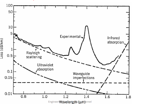
At the short wavelengths (Ultra violet region); Intrinsic absorption is
more dominant.
In IR region, the absorption peaks are present around the operating
wavelength range 700 nm to 1200 nm.
Basically an interaction between vibrating SiO band and
electromagnetic field of optical region takes place and it produces
intrinsic absorption.
EXTRINSIC ABSORPTION:-
Optical fibers are manufactured using melting techniques. During this
process, the metallic ions like 𝐶𝑢2+
, 𝐹𝑒2+
, 𝑁𝑖2+etc gets deposited.
These are metal element impurities, which causes absorption of incoming
photons and it is called as extrinsic absorption.
Similarly the OH ions form SiOH bond and it has fundamental absorption
at 2700 nm.
But the harmonics of these fundamental frequencies at 1380 nm, 1250
nm and 950 nm also produces extrinsic absorption.
This type of absorption can be reduced by reducing amount of impurities
and by reducing level of OH ions.
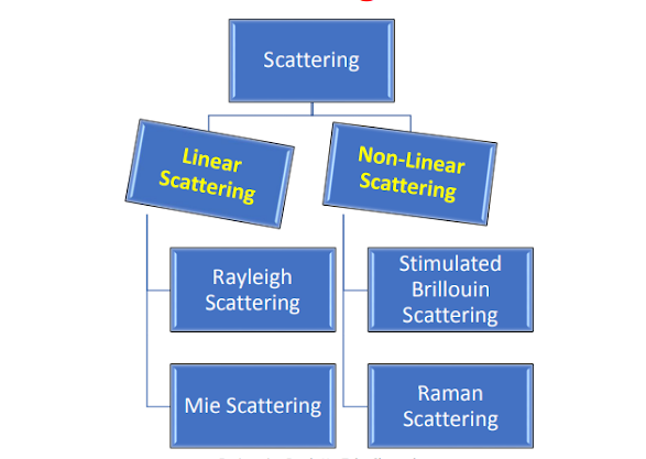
SCATTERING :-
Outlines :-
Basics of Scattering
Classification of Scattering
Linear Scattering
Rayleigh Scattering
Mie Scattering
Non Linear Scattering
Stimulated Brilliouin Scattering
Stimulated Raman Scattering
Basics of Scattering:-
Due to non uniformities in fiber optic cable; a straight line path of light rays
gets deviated. It is referred as scattering.
In case of optical cable; some of the optical power from one propagating
mode gets transferred to another mode.
This transfer of power takes place through the leaky or radiation mode.
This leaky mode does not continue to propagate with in the fiber core, but it
is radiated out from the fiber. It is scattering loss.
This loss are mainly caused by interaction of light with density fluctuations
within a fiber.
Basically the glass is composed of randomly connected network of
molecules, which is made up of several oxides and it increases the
compositional fluctuations.
In case of multimode fibers, there is a higher dopant concentration and
greater compositional fluctuations. Thus scattering losses are more.
CLASSIFICATION OF SCATTERING LOSS :-
In case of Linear Scattering optical power transferred from one
mode to another mode. But there is no change in frequency on the
scattering.
There are two types of linear scattering .
Rayleigh Scattering.
Mie Scattering.
Rayleigh Scattering:-
The light from the sun is scattered in atmosphere to give the sky color blue.
Rayleigh scattering in the glass is having same phenomenon and this scattering takes place in all
directions.
The Rayleigh scattering produces attenuation in the light rays and this attenuation is proportional to
1
𝜆
4
. Where 𝜆 is optical wavelength.
Thus if we transmit the data through the fiber optic cable at lower wavelength; the scattering is
minimized.
The Rayleigh scattering coefficient is denoted by 𝛾𝑅
Mie Scattering:-
The scattering caused by hologenetic which are comparable in size with
guided wavelength are called as Mie scattering.
This is a linear scattering which is always in forward direction.
Factors responsible for Mie scattering are as follows.
Cylindrical structure of cable is not perfect.
Imperfection of core and cladding interface.
Core and cladding refractive index is not uniform through out of fiber.
There are fluctuation in core diameter.
Due to Bubble or strain in fiber.
Mie scattering results significant attenuation depending upon fiber material,
size, design and manufacturing process. It can be reduce by following steps.
Removing imperfections during glass manufacturing process.
Controlling the coating of fiber.
Increase refractive index difference Engineering Funda YouTube Channel between core and cladding.
Non Linear Scattering:-
When the optical power is transferred from one mode to other
mode or same mode with different frequency; Non Linear scattering
happens.
This scattering takes place either in forward or backward direction.
It produces optical gain but there is a shift in frequency.
This shift in frequency results loss of signal and creates attenuation.
There are two types of Non linear scattering:-
Stimulated Brilliouin Scattering
Stimulated Raman Scattering
Stimulated Brilliouin Scattering:-
When the laser light beam is travelling in optical cable; there are variations
in an electric field of this beam.
These variations in electric field produces acostic vibrations in the optical
cable.
That means incident photon of acostic frequency as well as it produces a
scattered photon.
This type of scattering is called as stimulated Brillouin scattering and this
scattering is usually in opposite direction to that of incoming beam.
The scattered light looks like upper and lower sidebands, which are
separated from the incident light by the modulation frequency.
During this scattering, a frequency shift is produced which varies with the
scattering angle. This frequency shift is maximum in the backward direction.
Stimulated Raman Scattering SRS:-
Raman scattering basically represents inelastic scattering of photons.
When a laser light is travelling through optical cable; the spontaneous
scattering takes place.
In this process, some of the photons are transferred to the near frequencies.
When the scattered photons lose their energy then it is called as stokes shift
and when the scattered photons gain energy then it is called as antistokes shift.
But if the photons of other frequencies are already present then the scattering
of such photons takes place and in this case the two photons are generated. It is
called as stimulated Raman Scattering.
This scattering is similar to Simulated Brilliouin Scattering but in SRS instead of
acaustic photon; a high frequency optical phonon is created.
SRS can occur in both forward and reverse direction.
Fiber Bending Loss:-
Outlines:-
Basics of Fiber Bending Loss
Types of Fiber Bending Loss
Macroscopic Bending Loss
Micro bending Losses or Mode Coupling Losses
Basics of Fiber Bending Loss:-
If there is abrupt change in the radius of curvature of fiber; then the radiation loss takes place from fiber.
If there is sharp bend of the fiber then there is a probability of mechanical failure of optical cable.
Usually the higher order modes are not tightly bound to the core layer; so due to the sharp bends, the radiation losses of such modes take first.
Types of Fiber Bending Loss:-
There are two types of fiber bending losses
1. Macroscopic bending losses
2. Microbending Losses or Mode coupling Losses
Macroscopic Bending Loss:-
Macroscopic Bending Loss:- There is a radiation loss, when the radius of curvature of bend is greater
than the diameter of fiber. Such losses are also referred as large radius
losses.
As the radius of curvature of bend decreases, such losses increase
exponentially.
There is a certain critical value of radius of curvature upto which such
losses can be observed.
In optical cable; the wavefornt perpendicular to the direction of
propagation must be maintained to achieve this the part of mode, which
is on the outside of bend has to travel faster.
It indicates that, the light rays travelling through cladding; should travel
faster.
It is not possible, so the energy associated with that part is lost through
radiation.
Microbending Losses or Mode Coupling
Losses:-
Microbending Losses or Mode Coupling
Losses:- These are the losses due to small bending or small distortion.
If there are small fluctuations in the radius of curvature of fiber axis, then
microbends are created and light rays radiate out from these microbends.
The Microbends are formed due to two main reasons:
Non uniformities in the core radius, while manufacturing the cable.
During the cabling of fibers, non uniform lateral pressure can be created.
To minimize the losses due to microbends we should takes following steps:
While manufacturing the cable; a precise control of core diameter is maintained. A compressible jacket is fitted over the fiber, so that when the external pressure is
applied then the deformation of jacket place and there will not be creation of
microbends in the core layer of fiber.
Dispersion Loss in Optical
Fiber:-
Outlines:-
Basics of Dispersion Loss
Types of Dispersion Loss
Intramodal Dispersion
Types of Intramodal Dispersion
Material Dispersion
Wave Guide Dispersion
Intermodal Dispersion
Basics of Dispersion Losses :-
Dispersion is basically one of the limiting factors which decides, how
much data can ne transmitted through optical cable.
Due to dispersion, broadening of the output pulse takes place as well as
there can be Inter Symbol Interference ISI.
All these factors, limit the information carrying capacity of optical cable.
The two major sources of dispersion are material dispersion and
waveguide dispersion.
Material dispersion arises due to frequency dependent response of a
material used to manufacture the cable.
When the speed of wave in a waveguide depends on its frequency then
waveguide dispersion takes place.
Types of Dispersion Losses:-
There are two types of dispersion:-
1. Intramodal Dispersion
2. Intermodal Dispersion
Intramodal Dispersion Losses:-
The light source is used at input side. This converts an electrical
signal into optical signal.
But this light source does not emits single wavelength.
In actual practice, this light sources emits band of wavelength. If the
LED is used as lights source then this problem is more savior.
So the different spectral components will reach at the output at
different times.
This gives the spreading of output pulse. This is called as Intramodal
dispersion.
Types of Intramodal Dispersion Losses:-
There are two types of Intramodal dispersion
1. Material Dispersion
2. Waveguide Dispersion
Material Dispersion Losses:-
The material dispersion depends on the refractive index of material used to
manufacture the fiber cable.
The group velocity is the function of wavelength of light and the group
velocity is also the function of refractive index of the material.
Now depending on the light source, each spectral component of input
source will be having different wavelength.
Thus each component is traveling with different speed through optical fiber.
This gives the spreading of the output pulse.
This is called as the material dispersion. It is denoted by 𝐷m.
Material Dispersion Losses:-
It is given as
𝐷𝑚 =
𝜎𝑚/𝐿𝜎𝜆
Where,
𝜎𝑚 = width of pulse spread because of material dispersion
𝜎𝜆 = Spectral width of source
L = length of fiber cable
In terms of wavelength
𝐷𝑚 =
𝜆𝑆0/4 [1 − (𝜆0/𝜆)] 4
Where,
𝑆0 = Zero Dispersion slope
𝜆0 = Zero dispersion wavelength
It is also given by
𝐷𝑚 =
𝜆/𝑐 |𝑑
2𝑛/𝑑𝜆
2 |
Where, 𝑛 = Refractive Index
Wave Guide Dispersion Losses:-
Whenever the optical signals are passing through the fiber optic cable, then the
optical cable is acting as wave guide.
Now there is a variation in the wavelength of each spectral component emitted
from the source.
As well as the angle made by each light ray with respect to the axis of optical cable
will be different.
Because this angle is the function of wavelength of light.
Since there is variation in the angles, all the light rays are not reaching to the
output at the same time.
This gives dispersion at the output. This is called as waveguide dispersion.
In case of multimode fibers almost all the light rays are travelling away from cut off
axis.
So in this case the waveguide dispersion is negligible.
Waveguide Dispersion Losses ;-
It is given as
𝐷𝑤 =
𝜎𝑤 /𝐿𝜎𝜆
Where,
𝜎𝑤 = width of pulse spread because of waveguide dispersion
𝜎𝜆 = Spectral width of source
L = length of fiber cable
Intermodal Dispersion Losses:-
This type of dispersion is also called as ‘Modal Dispersion’
This dispersion takes place in case of multimode fiber optic cables.
Here the different mode are travelling with different group velocities inside an
optical fiber.
Some modes are travelling with maximum speed, while some are travelling with
minimum speed.
Thus there is difference between the transit time of these modes.
So all the modes are not coming to the output at the same time.
This gives spreading of output pulse.
This type of dispersion is called as intermodal dispersion.
In case of multimode step index fiber, this dispersion is highest.
It can be reduced by choosing an optimum refractive index profile.
In case of graded index fiber it is less by factor of 100 times.
For single mode fiber, it is almost zero.